This post contains affiliate links. For more information, see my disclosures here.
As I mentioned in the previous article, in this second part I am going to install a battery in the system and also design a box to organise everything.
 JV Lobo
🔋 To power the system I thought about reusing an old iPhone battery that I had lying around.
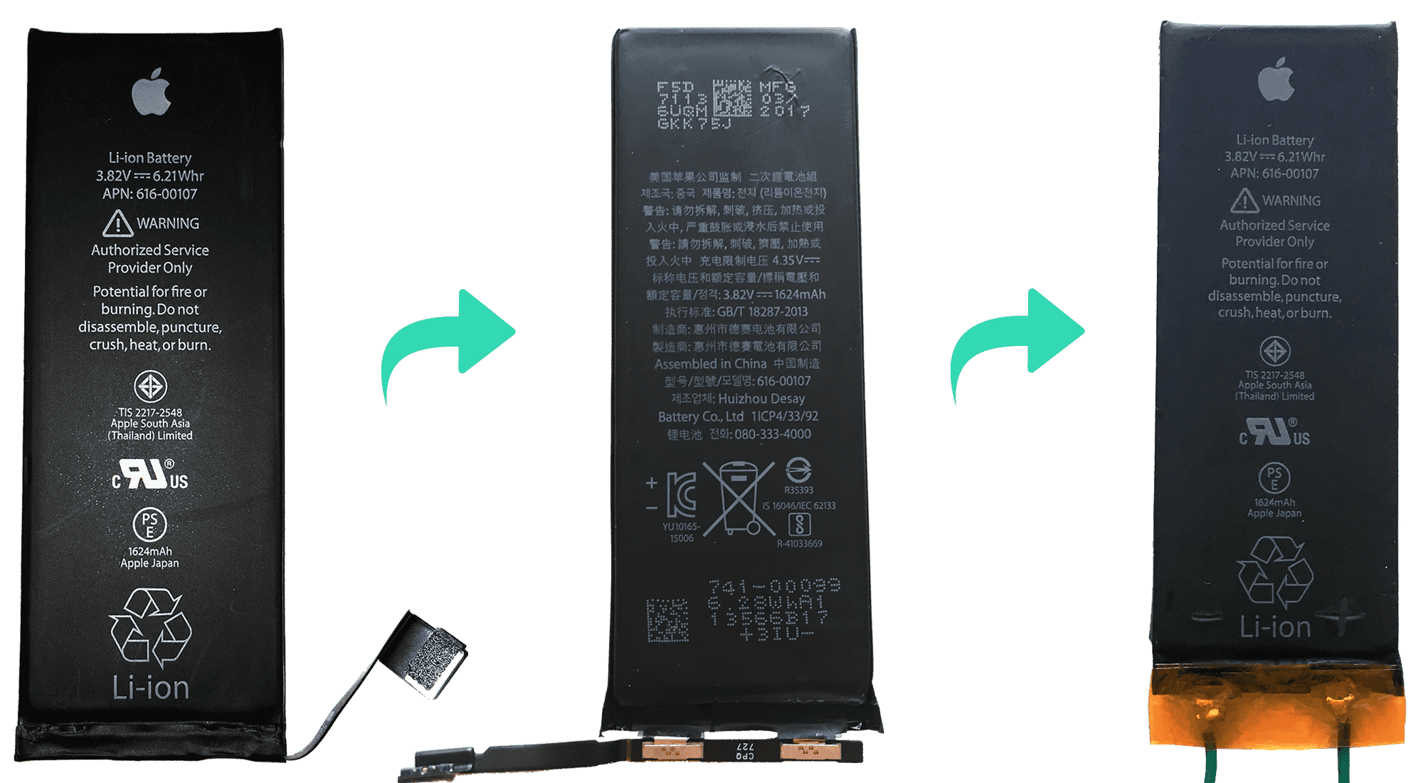
If you take a closer look at an iPhone battery, at first you may think that it has a strange connection and that it cannot be reused, but it really is a lithium battery like any other, with its positive and negative terminals, only they are hidden under the adhesive tape.
If we remove this tape, you can clearly see the two terminals and the small board that Apple uses along with its connector.
It is only needed to remove this part and check which one is the positive terminal and which one is the negative (with the help of a multimeter) and solder a pair of wires:
But of course, with this we can provide power to the circuit until the battery charge is used up, but then what? How can we recharge the battery? 🔌
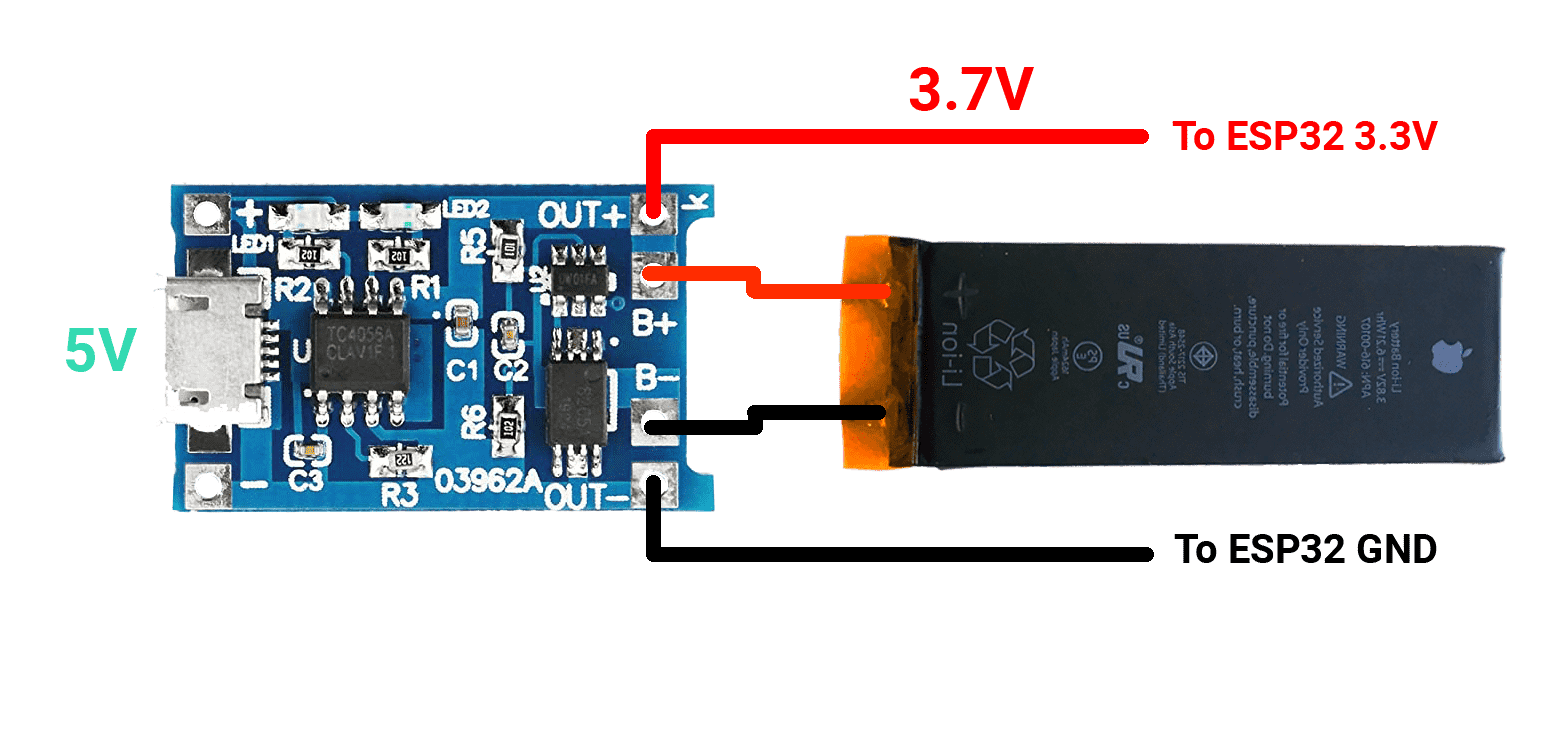
For this there are some small boards called lithium battery charging modules, which usually come with mini-USB or micro-USB input, and soldering the terminals to this module serve to recharge the battery. They also include charge and discharge protection.
This board comes with two output terminals that are the ones that we will connect to our circuit.
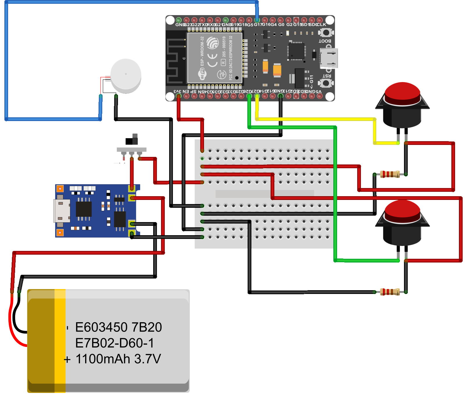
The assembly scheme would look something like this:
👩🏽🎨 The next step is to design the box in 3D.
About a year ago I bought the Ender 3 Pro and I have been printing in 3D ever since but when I have designed things I have always done it on Tinkercad which is very easy to use and offers quite good results. For this project I wanted to learn how to use Fusion 360 which offers more possibilities and with which you can make somewhat more complex designs.
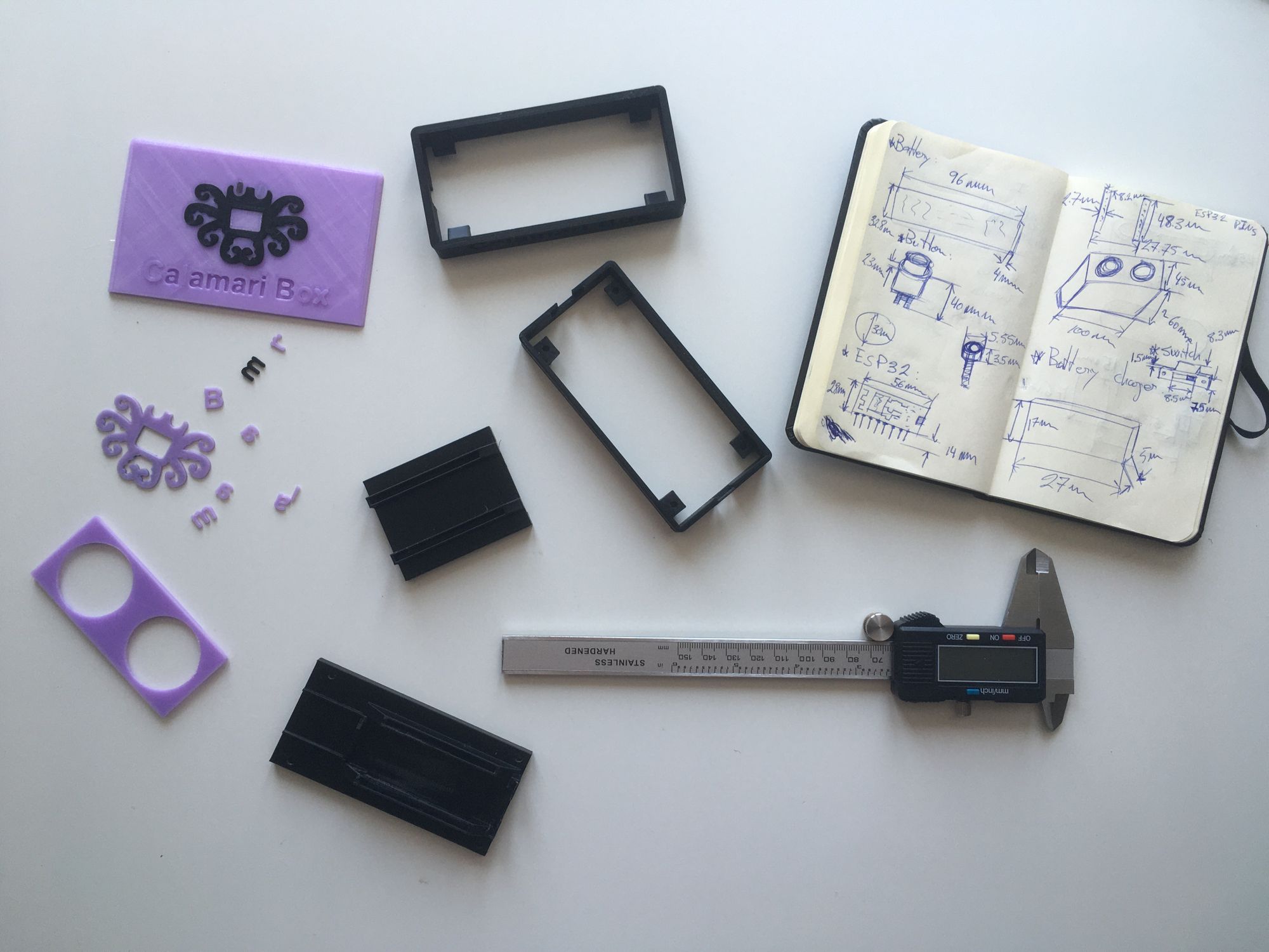
The first thing I do when I'm going to design something is obviously take measurements 📐. I always use my caliper, the most accurate tool for this task.
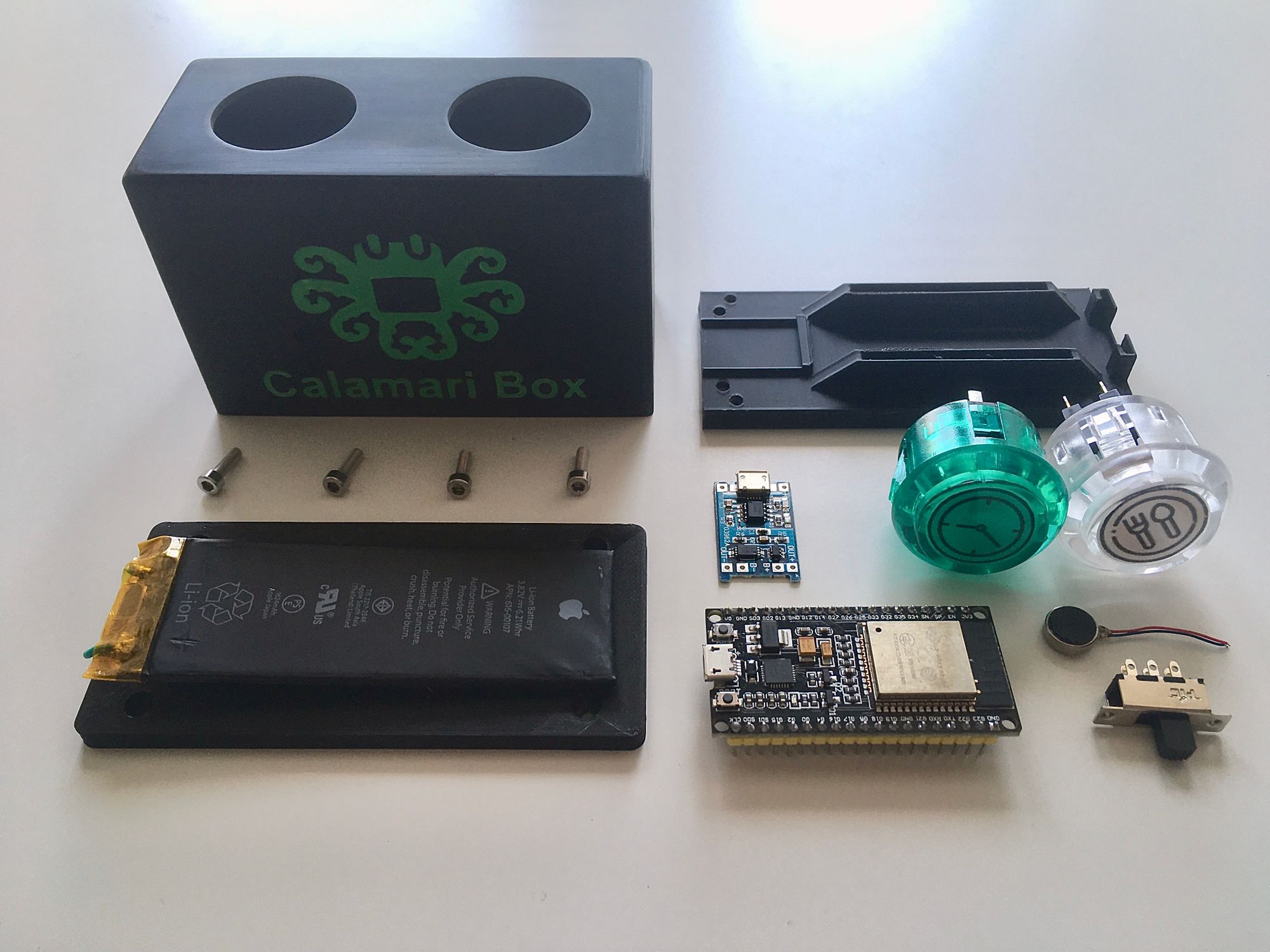
I took the measurements of all the components that will go inside the box. I am going to use two large buttons, the ones used in old arcade machines. I will also put a switch to turn the system on and off. I will install a small vibration motor so that, after pressing any of the buttons, I will receive confirmation when the action has been carried out correctly.
For the box I had a fairly simple structure in mind: rectangular with two button holes on the top, a micro-USB port on one side for charging and a switch to turn the system on or off on the other side.
After quite a few hours learning and designing with Fusion 360 I came up with something that I was comfortable with 👍🏾:
This is a three-piece design:
- The upper part, where the buttons go, and that has enough height to house the components inside.
- A part with supports to host the electronic components and with space underneath to accommodate the battery.
- The bottom lid, used to close the box and put the screws that will also go through the other two parts so that everything is securely fastened.
When I design this type of pieces in 3D, instead of designing and printing everything at once without knowing if they are going to fit well (which takes a long time and uses too much filament), what I usually do is print small sections that I consider "critical". They are parts that because of where they are or the way I have designed them, I am not sure if they will turn out as I have in my mind 🤔. Because when you are designing, everything is "perfect", but once it is printed it doesn't turn out as it does in the design. Also there are things that may not be well designed or need to be redesigned to make them look better. You also have to take into account the tolerances between different pieces that fit or are next to each other, because the printed material is not perfect, and usually it will have a greater thickness than the one you have designed.
In this design, for example: the part such as the holes for the buttons, the part where the components are mounted, the top part in the area where it connects to the other two parts or the part of the logo and the letters. These parts to my understanding were the most critical ones and I printed small sections to be able to check and correct errors. And thank goodness I did it, because I had to redesign certain parts 😅.
Here you can see the measurements I took and the parts I printed to check and correct in the design:
Finally, with all the parts well designed I was able to print everything, which took quite some time ⏳:
- Top piece: about 11 hours and about 20 meters of filament.
- Centerpiece: about 4 hours and about 6 meters of filament.
- Bottom piece: about 7 hours and about 11 meters of filament.
- Letters and logo: less than 1 hour and over 1 meter of filament.
After printing all the pieces I had to sand them, especially the front part where the logo and letters go.
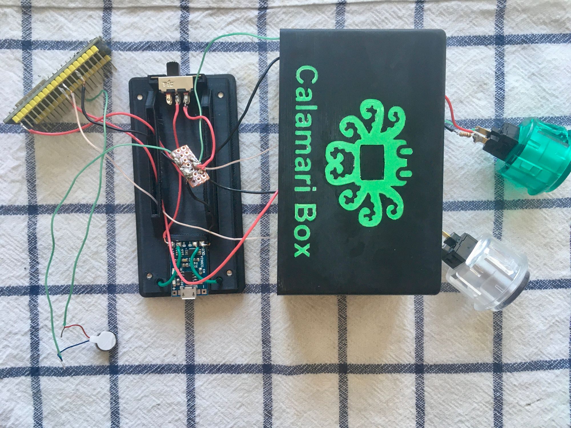
Finally the moment I was looking forward: the final assembly! 👨🏽🔧
Although the buttons are different, they are still connected to the same pins as in the prototype: 26 to start/end the shift and 27 to start/end the lunch break. The vibration motor will be connected to pin 17.
The tip of my soldering iron is very worn, which made it difficult for me to make a good solder.
After much soldering and connecting cables:
With everything connected, and before closing the box, I had to make some adjustments to the code.
First, to control the vibration motor. It is very simple, I just configured pin 17 as output and each time a button is pressed, separate signals are sent to the motor in different time ranges so that it makes a vibration pattern. I have created two patterns: one for when the shift or the lunch break starts and the other for when it ends. You can see it in version 2 of the source code that I will leave in a link at the end of the article.
Besides, since the system is going to be connected to the battery and since it is only going to perform the action when one of the buttons is pressed, ideally it should not be working all the time. For this you can make use of the deep sleep function of the ESP32 💤. It is very simple to configure, the idea is that once the system boots, it goes into sleep mode, and only wakes up when one of the buttons is pressed. Depending on the button pressed, it will perform the corresponding action and once it is finished, it returns to deep sleep mode.
 Alain
Alain
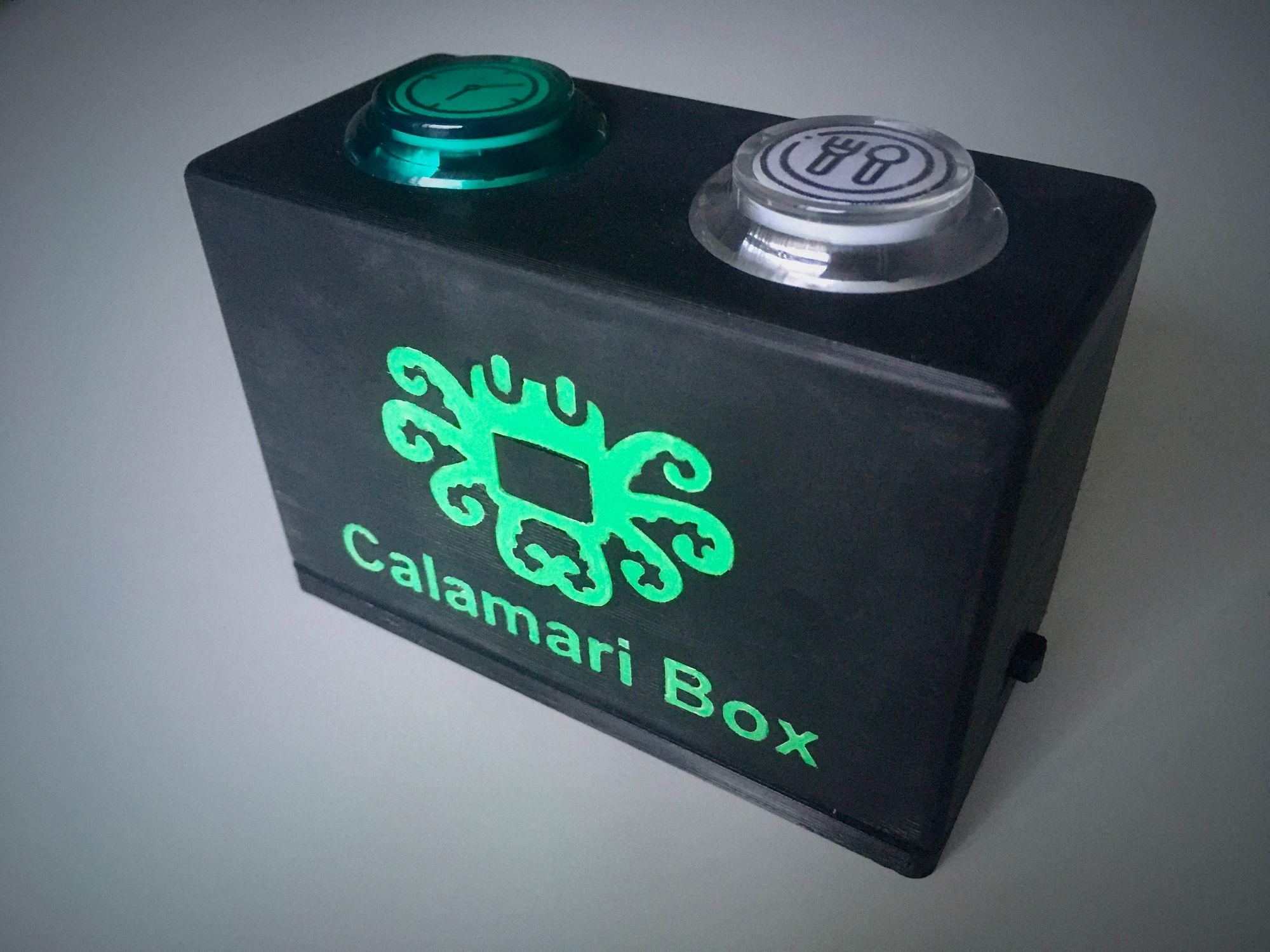
And this is it, once the new code was uploaded to the board, it was time to put the screws in and see the final result.
And here you can find the new part of the code, it is in the v2 branch.
 jvlobo
The final test:
It works!! 🎉